
| Menu level 1 | Menu level 2 | Menu level 3 | Description |
|---|---|---|---|
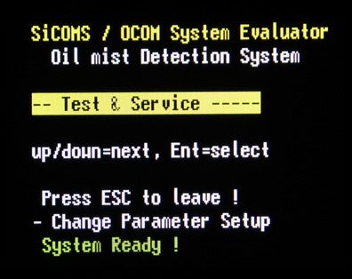 Test & Service | View and change Evaluator test options and perform service procedures. Press [Enter] to switch to the sublevel: PIN for Setup must be entered in “Setup CPU” menu before using Test & Service menu. Otherwise, the following warning appears: P?? |
Table 1 Setup Parameter Details Menu Structure 4.7.1, page 4.6
| Menu level 1 | Menu level 2 | Menu level 3 | Description |
|---|---|---|---|
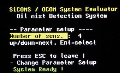 Number of sens | Number of connected OMD sensors in the range of 1 to 16. Default is 16. | ||
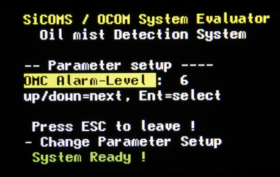 OMC Alarm-Level | Main alarm level for oil mist concentration in the range of 1 to 10. Default is 7, which corresponds to 2.5 mg/l. | ||
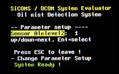 OMC Alarm-Level2 | Main alarm level for oil mist concentration at an alternative sensor location (f.i. a sensor in the gear box) in the range of 1 to 10, or Off. “Off” value means that main alarm for this location is disabled which is default. | ||
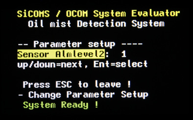 Sensor Almlevel2 | Main alarm level for oil mist concentration at an alternative sensor location (f.i. a sensor in the gear box) in the range of 1 to 10, or Off. “Off” value means that main alarm for this location is disabled which is default. | ||
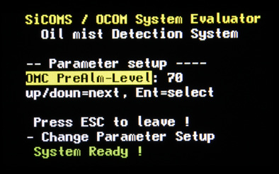 OMC PreAlm-Level | Pre-alarm level for oil mist concentration in percents of main alarm level. Range of possible values: 20% to 100%. Default value is 70%. | ||
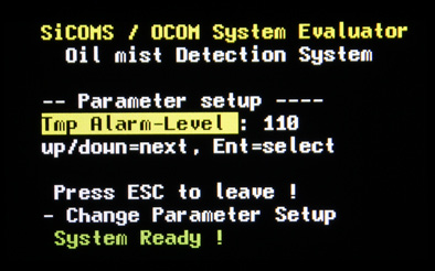 Tmp Alarm-Level | Temperature main alarm level in °C. Range of possible values: 10°C to 130°C with step 10°C, or 0 = Off. If “Off” is entered, temperature alarm is disabled. Default: 110°C. | ||
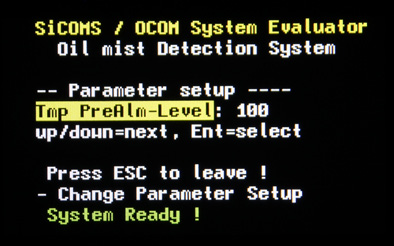 Tmp PreAlm-Level | Temperature pre alarm level in °C. Range of possible values: 20°C to 130°C. Default is 100°C. | ||
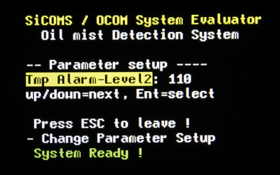 Tmp Alarm-Level2 | Main temperature alarm level for an alternative sensor location (e.g. a sensor in the gear box) in the range of 20°C to 130°C with step 10°C. If “Off” is entered for OMC Alarm-Level2, temperature alarm is also disabled. Default: 110°C. | ||
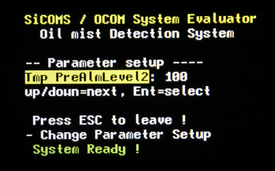 Tmp PreAlm-Level2 | Temperature pre alarm level for an alternative sensor location (e.g. a sensor in the gear box) in °C. Range of possible values: 20°C to 130°C. Default is 100°C. | ||
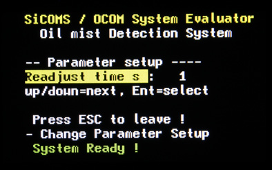 Readjust time s | Time in seconds assigned for readjusting the reference value if signal intensity at light measuring sections becomes higher. Range of possible values: 1 to 600 sec. Default is 1 sec. | ||
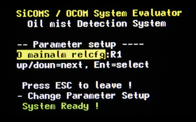 O mainalm relcfg | Relay configuration for opacity main alarm. Possible values: R1, R1 + 2 (R1 = Relay 1, R1 + 2 = both Relay 1 and Relay 2). Default is R1. | ||
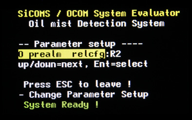 O prealm relcfg | Relay configuration for opacity pre alarm. Possible values: OFF, R1, R2, R1 + 2 (R1 = Relay 1, R2 = Relay 2, R1 + 2 = both Relay 1 and Relay 2). Default is R2. | ||
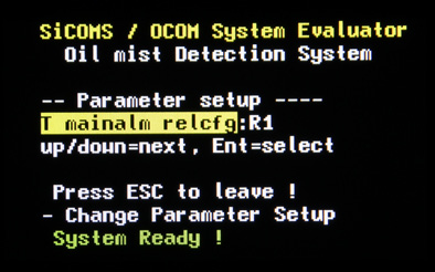 T mainalm relcfg | Relay configuration for temperature main alarm. Possible values: OFF, R1, R2, R1 + 2 (R1 = Relay 1, R2 = Relay 2, R1 + 2 = both Relay 1 and Relay 2). Default = R1. | ||
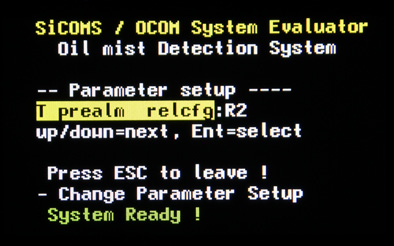 T prealm relcfg | Relay configuration for temperature pre alarm. Possible values: OFF, R1, R2, R1 + 2 (R1 = Relay 1, R2 = Relay 2, R1 + 2 = both Relay 1 and Relay 2). Default is R2. | ||
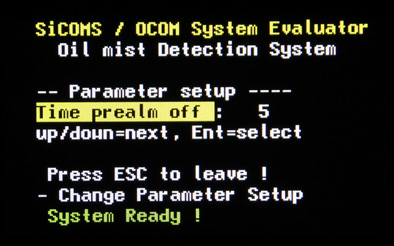 Time prealm off | Time in seconds for automatic reset of pre-alarm. Range of possible values: 1 to 60 seconds. Default is 5 sec. | ||
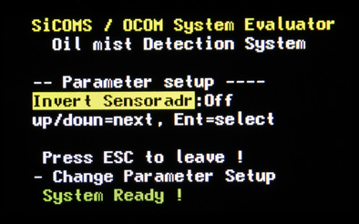 Invert Sensoradr | On – assign the sensor numbers in reverse order. This can be used to match sensor numbers to engine compartment numbers. Off – keep the default sensor numbers (default). Attention: By pressing [Enter] to confirm the selection, the Evaluator will be restarted. | ||
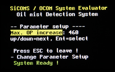 Max. OP increase | Maximal transmission signal change per sampling interval. This is used as a filter for signal disturbances, f.i. carbon particles. Possible values: 10 to 1000, given in digits pro sampling. Default: 60. | ||
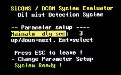 Mainalm dly sec | Time delay in seconds before the system triggers main alarm. This setting helps to avoid triggering main alarm when the main alarm level is exceeded only for a short time. Default: 3 sec. | ||
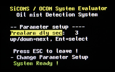 Prealarm dly sec Prealarm dly sec | Time delay in seconds before the system triggers pre alarm. This setting helps to avoid triggering pre alarm when the pre alarm level is exceeded only for a short time. Default: 3 sec. | ||
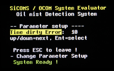 Time dirty Error | Time delay before the system will change sensor status to “Dirty” when the corresponding conditions are met. Possible range: 1 – 240, default: 10 sec. | ||
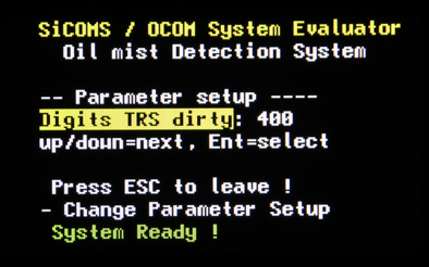 Digits TRS dirty | Threshold for transmission value in digits. If the transmission decreases below this limit, the system interprets this as contamination at the light measurement section (LED becomes “dirty”). Possible range: 250 – 800, default: 400. | ||
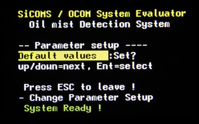 Default values: Set? | Reset all settings to factory defaults. Attention: This will delete all specific settings for the system after which the system might stop working correctly. At least the number of connected sensors has to be corrected after reset to factory defaults. |
Table 2 COT measure setup Details Menu Strucuture 4.7.2, see page 4.7
| Menu level 1 | Menu level 2 | Menu level 3 | Description |
|---|---|---|---|
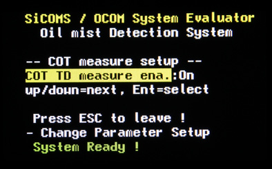 COT TD measure ena. | On – enable COT temperature difference measurement (COT temperature menu xxxx is displayed). Off – disable COT measurements and hide the COT temperature menu. | ||
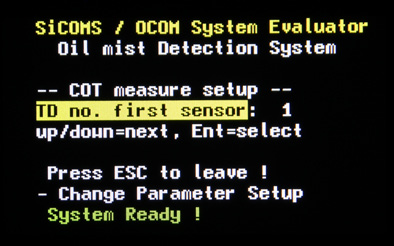 TD no. first sensor | The number of first sensor that is used in COT temperature difference measurement. | ||
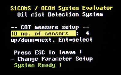 TD no. of sensors | The total number of sensors involved in COT temperature difference measurement. | ||
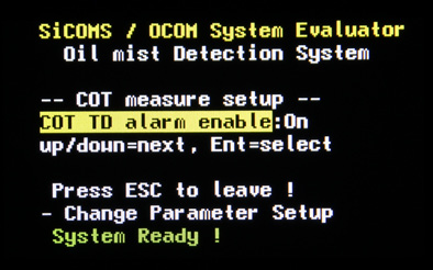 COT TD alarm enable | On – enable alarm activation if COT TD alarm condition is met. Off – COT TD alarm will be not activated. | ||
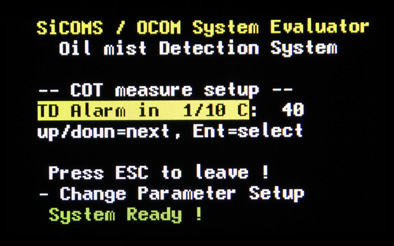 TD Alarm in 1/10 C | Difference between sensor temperatures and the average sensor temperature in 1/10 of °C that activates COT TD main alarm. Possible range: 10 – 150. Default: 50. | ||
 TD PreAlm in 1/10 C | Difference between sensor temperatures and the average sensor temperature in 1/10 of °C that activates COT TD pre-alarm. Possible range: 10 – 150. Default: 40 | ||
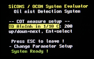 TD Alminh in 1/10 C | Temperature threshold in 1/10 of °C. If the average sensor temperature is lower than this limit, COT TD alarm triggering is inactive. Possible range: 10 – 800. Default: 300. |
Table 3 Setup Alminhibit Parameters Details Menu Structure 4.7.3, page 4.7
| Menu level 1 | Menu level 2 | Menu level 3 | Description |
|---|---|---|---|
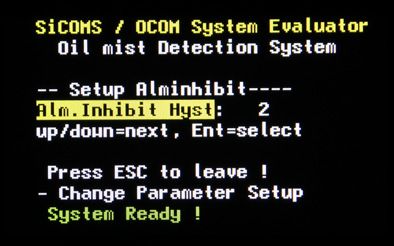 Alm.Inhibit Hyst | Alarm inhibit hysteresis in °C. Defines how much the sensor temperature is allowed to drop after reaching the threshold for alarm inhibit without affecting the alarm status. Possible values: 1°C to 15°C. Default: 2°C | ||
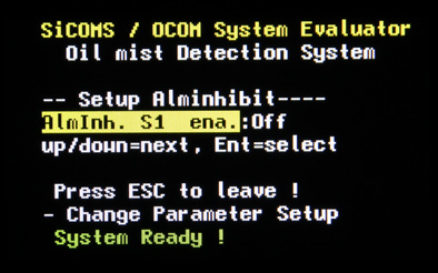 Alminh. S1 ena. | Alarm inhibit for sensor 1. “On” means enabled, “Off” – disabled. Default: “Off”. | ||
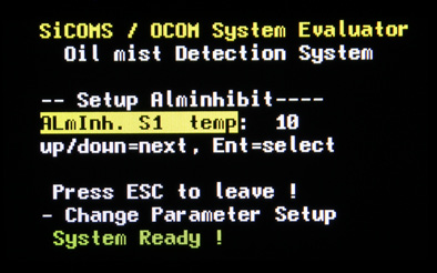 Alminh. S1 temp | Temperature threshold for alarm inhibit for sensor 1 in the range of 2°C to 80°C. No alarm will be triggered if sensor temperature has not reached the threshold after engine start. Default: 10°C. | ||
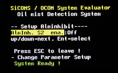 Alminh. S2 ena. | Alarm inhibit for sensor 2. “On” means enabled, “Off” – disabled. Default: “Off”. | ||
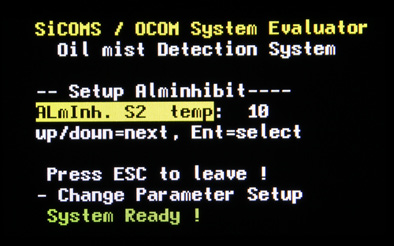 Alminhi. S2 temp | Temperature threshold for alarm inhibit for sensor 2 in the range of 2°C to 80°C. No alarm will be triggered if sensor temperature has not reached the threshold after engine start. Default: 10°C. … (Menu items “AlmInh. S[n] ena.” and “AlmInh. S[n] temp.” are repeated for each sensor up to S16) |
Table 4 Setup CPU Details Menu Structure 4.7.4, see page 4.7
| Menu level 1 | Menu level 2 | Menu level 3 | Description |
|---|---|---|---|
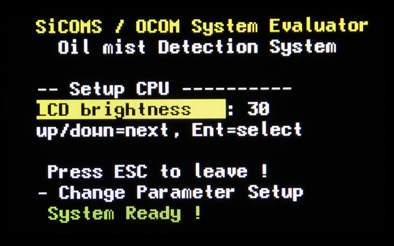 LCD brightness | Brightness of Evaluator LCD display in the range of 5 to 100. The greater the value, the higher is the brightness. Default is 30. | ||
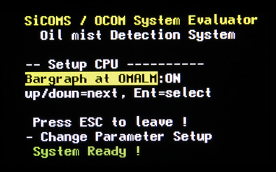 Bargraph at OALM | Optionally display the bar graph if an alarm is triggered by the system. ON – display the bar graph, which is default. OFF – display the default screen | ||
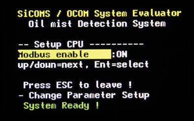 Modbus enable | Status of Modbus interface. ON – enabled, OFF – disabled. | ||
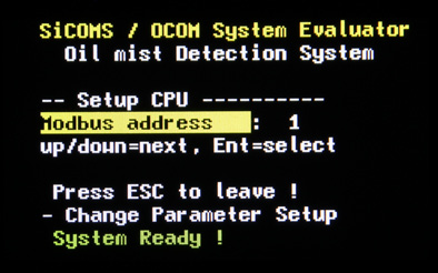 Modbus address | Modbus address of the Evaluator in the range of 0 to 99 | ||
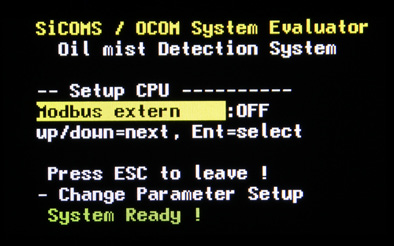 Modbus extern | ON – The Modbus data will be sent out via connector 3 OFF – The Modbus data will be used internally, i.e. for installed CAN interface For internal use Modbus address has to be set to “1”! | ||
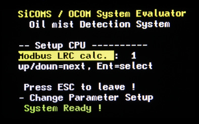 Modbus LRC calc | Modbus LRC calculation method. Possible values: 0 – disabled 1 – ASCII (default) 2 – binary. | ||
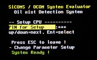 PIN for Setup | The user must enter this PIN in order to be able to change system values and to use “Test & Service” menu. To enter PIN: press [Enter], the PIN field becomes highlighted. Use [▲] and [▼] buttons to increase or decrease the value. When the correct PIN appears in the value field, press [Enter] again. The screen appears then, and the system parameters can be changed now. If wrong PIN was entered, text in the PIN field will be changed to “P??”. | ||
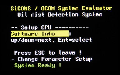 Software Info | Firmware version of the Evaluator (read-only). |
Table 5 Test & Service Details Menu Structure 4.7.5, page 4.7
| Menu level 1 | Menu level 2 | Menu level 3 | Description |
|---|---|---|---|
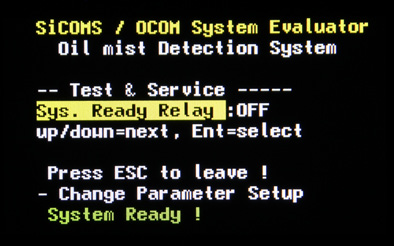 Sys. Ready Relay Sys. Ready Relay | The Ready Relay can be switched on and off manually for testing purposes | ||
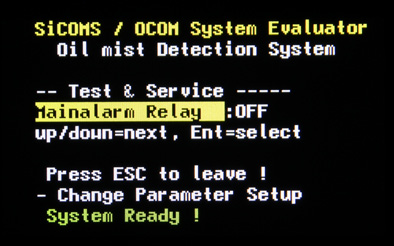 Mainalarm Relay | The Relay 1 (usually used as Main Alarm relay) can be switched on and off manually for testing purposes. | ||
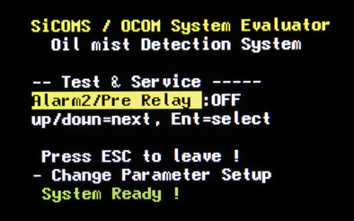 Alarm2/Pre Relay | The Relay 2 (often used as pre-alarm relay) can be switched on and off manually for testing purposes. | ||
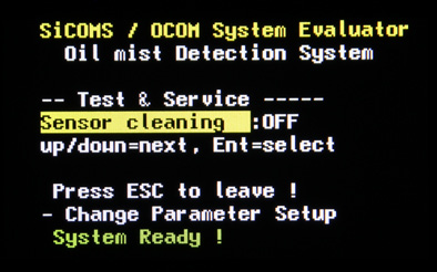 Sensor cleaning | OFF – default. System works in accordance with specification. ON – as soon as ON is selected, the system enters a special maintenance mode where alarms will not be triggered until the system restarts. This is used when sensors need to be pulled out of the engine and cleaned. After cleaning press [Esc] button; sensors will be calibrated automatically and then the system restarts.! Attention By pressing [Esc] button the Evaluator will recalibrate the whole sensor chain. This requires that all sensors of the chain are cleaned (not only several sensors)! | ||
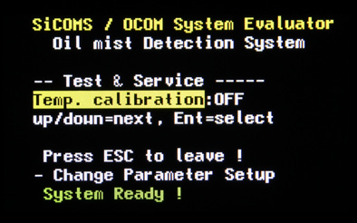 Temp. calibration | OFF – default. System works in accordance with specification. ON – as soon as ON is selected, the screen awaits user input of calibration temperature. Press [▲] or [▼] buttons to set the correct temperature of the sensor environment. Initial value is 60°C. Possible range: 20°C – 90°C. Pressing [Esc] leaves the current sensor temperature unchanged. On pressing [Enter] the system calibrates sensor temperatures, the message “Calibrating temperature busy!“ appears. After successful calibration the system restarts automatically. | ||
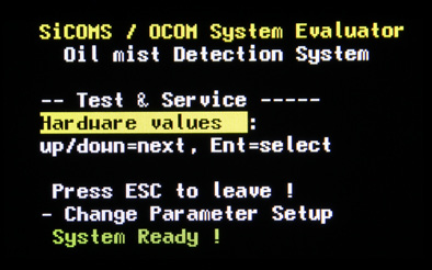 Hardware values | The screen displays some information about Evaluator hardware. |