BeCOMS® – Test Features

Menu level 1Menu level 2Menu level 3Description

To get access to this menu, a PIN must be entered (see Table 2 on page 4.11).  View and use test features of the Evaluator. (see Table 3 on page 4.12)
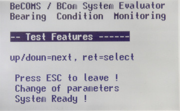
Test Features
 To get access to this menu, a PIN must be entered (see Table 2 on page 4.11).
 
View and use test features of the Evaluator. (see Table 3 on page 4.12)

Table 1 Setup Parameter Details

Menu level 1Menu level 2Menu level 3Description


TS Alm-Level DC TS Alm-Level DCThe value of DC main alarm level in the range of 0 to 5. The higher the value, the less sensitive is the system. The 0 value disables the DC alarm.
TS PreAlm-Level
TS PreAlm-Level
The value of DC pre-alarm level in percents of DC main alarm.
Possible values: 40 to 100.
RPM Alarm-Level
RPM Alarm-Level
The value of overspeed alarm in RPM.
Possible values: 0 to 3000, step 50.
The 0 value disables the alarm.
TS Alm-Level1 AC
TS Alm-Level1 AC
The value of AC main alarm level in the RPM zone 1.
Possible values: 0 to 5.
The 0 value disables the alarm.
TS Alm-Level2 AC
TS Alm-Level2 AC
The value of AC main alarm level in the RPM zone 2.
Possible values: 0 to 5.
The 0 value disables the alarm.
RPM for Level2
RPM for Level2
Engine rotation speed in RPM which defines the boundary between RPM
zone 1 and RPM zone 2.
Start Alminhibit
Start Alminhibit
Time interval in seconds immediately after engine start during which the main alarm is disabled.
TS Test Time
TS Test Time
Time interval between test pulses, possible values: 1 min to 10 min.
Test pulses help to check if the SRE sensor functions correct.
TS Test Len
TS Test Len
The length of test pulse.
Possible values: 1 s to 15 s.
IS Impuls Offset
IS Impuls Offset
The offset between TDC of cylinder 1 and the synchronisation pulse at
the channel 0.
 
This value cannot be set at the Evaluator using the “Up” and “Down” buttons. It is used during the impulse offset setup procedure as an indicator.
 
To start the procedure, a PIN must be entered (refer to Table 2 on page 4.11)
PIN Impuls Offs
PIN Impuls Offs
PIN for impulse offset setup, the procedure is the same as described in Table 2 on page 4.11
TSeff ena for DC
TSeff ena for DC
Enable or disable (values 1 and 0 accordingly) calculating effective value of thermosignal in percents of DC alarm level.
Values for TSeff
Values for TSeff
Number of points for calculating effective value of thermosignal in percents
of DC alarm level.
DC Alarm percent
Values for TSeff
Scale factor for DC alarm level, possible values: 80% to 199%.
AC Alarm percent
AC Alarm percent
Scale factor for AC alarm level, possible values: 80% to 199%.

Table 2 Setup CPU Details

Menu level 1Menu level 2Menu level 3Description
LCD brightness
LCD brightness
Brightness of Evaluator LC display in the range of 5 to 100. The higher the value, the brighter is the display.


LCD large font
LCD large font
Selection of font
 
0 = 7×12 System
1 = Consolas
2 = Lucidas Console
RS485 fullduplex
RS485 fullduplex
RS485 transmission mode. Possible values:
 
OFF:         two-wire mode. Sending and receiving data simultaneously is not possible.
ON:           four-wire  full-duplex  mode.  Allows  communication  in  both directions simultaneously.
Modbus enable
Modbus enable
Enable or disable (values ON and OFF accordingly) the Modbus interface.
Modbus address
Modbus address
Modbus address in the range of 0 to 99.
PIN for Setup
PIN for Setup
PIN for enabling write access to menu items in “Setup Parameter”, “Setup CPU” and “Test Features”.
 
To enter PIN: press [Enter], the PIN field becomes highlighted. Use [▲] and [▼] buttons to increase or decrease the value. When the correct PIN appears in the value field, press [Enter] again. This screen appears again, and the system parameters can be changed now. If wrong PIN was entered, text in the PIN field will be changed to “P??”.
Software InfoSoftware InfoFirmware version of the Evaluator (read-only).

Table 3 Test Features Details

Menu level 1Menu level 2Menu level 3Description

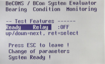
Ready Relay
Ready Relay
Switch the Ready relay ON and OFF
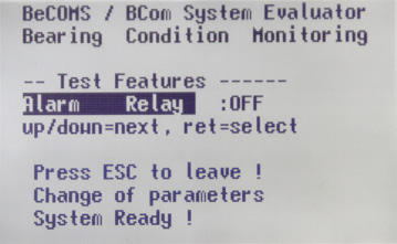
Alarm Relay
Alarm Relay
Switch the Alarm 1 relay ON and OFF.
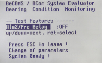
Alm2/Pre Relay
Alm2/Pre Relay
Switch the Alarm 2 relay ON and OFF.
Testsignal A
Testsignal A
Switch the test signal on channel A ON and OFF.
 
At the same time the values TS1 and TS2 are displayed (signals from the
first and the second thermovoltage measurement channels).
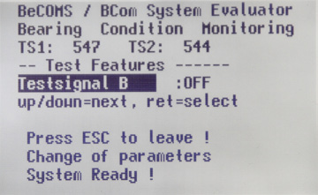
Testsignal B
Testsignal B
Switch the test signal on channel B ON and OFF.
 
At the same time the values TS1 and TS2 are displayed (signals from the
first and the second thermovoltage measurement channels).
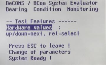
Hardware values
Hardware values
The screen displays some information about Evaluator hardware.
 
– temperature Mainboard
– temperature Display
– internal clock values
Nach oben scrollen